A-7410
AUTO CIRCUIT TRACER DETECTOR
Safety Instructions:
1. Only for testing DC voltage, don’t connect to circuit exceeding 42 volts DC under any circumstance.
2. Do not use on AC voltage.
3. Do not apply to any circuit, which directly or indirectly connect to AC lines or any other AC power source.
4. Do not apply to any components or circuits of the ignition system.
5. Before using this device, check the vehicle’s electrical writing and disconnect any part of the system, which is sensitive to voltage and current pulses such as air bags, electronic control modules, etc.
6. After you finish checking vehicle, make sure you have correctly restored all the connections which you had disconnected.
| 7. Always follow the instructions and procedures indicated in the vehicle’s service manual before attempting to disconnect any part or subsystem of the electrical circuit.
Exceeding the limits listed above when using this apparatus, or not observing the precautions listed above can expose you to physical injury and permanently damage your instrument, parts and circuits of the vehicle under test.
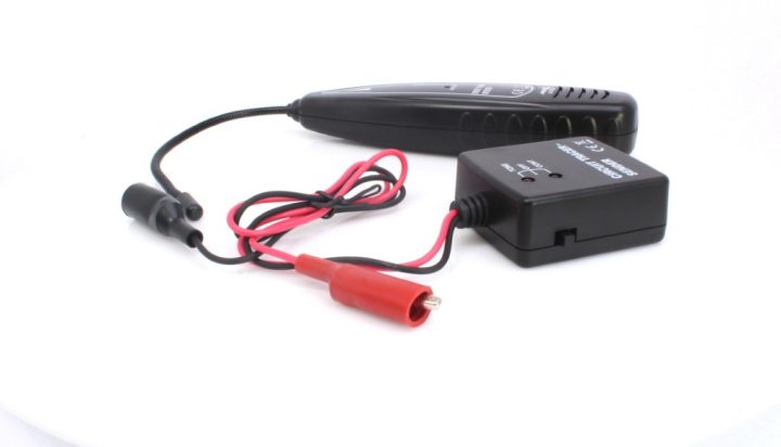
How to use the probe:
The probe of the receiver is built of coiled steel and may be bended as needed, which can help user to reach wires in congested or difficult areas. Depending on the circuit characteristic and receiver sensitivity setting, the probe will pick up the signal from the wire without direct contacting. However, to achieve the best possible defecting range, the receiver’s probe tip (black cap) shall touch the wire being traced; either above or below it. See Figure (1).
Self-Check:
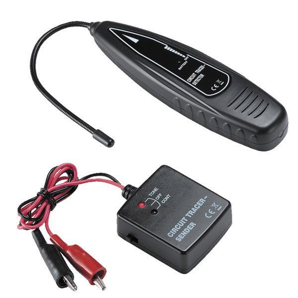
1. Set the witch of SENDER to “TONE”, the RED LED shall light up. If it’s not, please check the battery.
2. Switch on the RECEIVER, the RED LED shall light up. If it’s not, please check the battery.
3. Turn on the rotary switch. Approach the RECEIVER to the SSENDER. RECEIVER shall give audio signal. If yes, both RECEIVER and SENDER work fine.
Wire tracing:
NOTE!: Read the limits and safety precautions at time.
1. Connect the BLACK clip to the ground, RED clip to the traced wire. (Or if user needs series connection, connet the BLACK clip to the positive of the battery, RED clip to the traced wire.) See Figure (2).
2. Tune the sensitivity until user can hear the audio signal. Move the RECEIVER probe to the traced wire as close as possible.
3. By following the audio signal, user can trace the wire.
4. As RECEIVER moves alone the traced wire, if the audio signal disappears or suddenly becomes weak, that means open circuit or bad connection.
5. If is difficult or impossible to pick up the audio signal, please increase the sensitivity of the RECIVER and try again.
6. If user operates the RECEIVER inder noisy environment, user can hook up the ear phone with ear phone socket which is on the bottom of the receiver.
Checking for short circuit:
1. Disconnect the power to the wire to be checked and remove all the loads from this wire (for example: remove the lamp from the wire).
2. Set the switch of Sender to “CONT” position. Connect the test leads to a couple of wires which are to be checked.
3. When the resistance is less than 10k ohm, the green LED of “CONT” will light. With all the loads having been removed, the green LED’s lighting indicates that the couple or wires are in short circuit.
3d rotate